USB Board
The WILD USB-GPIO board is used for bench validation, external trigger logging, and timing integration with behavioral equipment. It provides a PC-connected GPIO path that can be used alongside WILD BLE control and logger-side digital inputs.
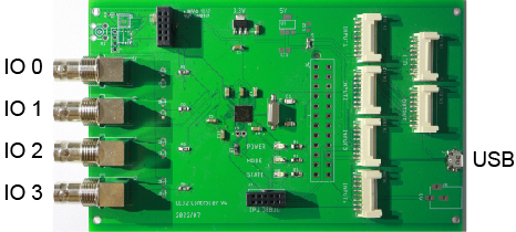
Interface
The board exposes four external I/O channels, labeled IO0 to IO3, and a USB connection to the host PC. The USB path is useful for recording external events at the PC, generating TTL outputs for external equipment, and validating synchronization behavior before animal recordings.
Fabrication Files
USB-GPIO board manufacturing files are available in PCB/USBboard.
| File | Purpose |
|---|---|
WILD_USB_2026-06-18.zip |
Gerber package for PCB fabrication. |
WILD_USB.xlsx |
BOM workbook for assembly review. |
WILD_USB.csv |
BOM export for manufacturer upload or quick inspection. |
WILD_USB.brd and WILD_USB.sch |
Eagle board and schematic source files. |
Windows Host Timing
The WILD device and the Windows acquisition PC use independent clocks. Keeping those clocks aligned matters when USB-GPIO trigger timestamps are merged with WILD logger events. Windows automatic time management does not calibrate drift against WILD time, and an automatic time correction can create an abrupt shift between the PC clock and the device clock during a recording.
For best synchronization accuracy with the USB-GPIO board on Windows, disable automatic time setting and automatic time-zone changes before the recording session. Download and run TimeCalibrator on the acquisition computer, then use the calibration record to correct PC-to-WILD time offset and drift after export.
Keep the raw USB-GPIO log, TimeCalibrator record, and corrected timestamp table with the WILD export so the synchronization correction can be audited later.
Supported Operations
| Operation | Direction | Use case | Timing note |
|---|---|---|---|
| TTL input logging | External equipment -> USB-GPIO -> PC | Log camera, behavior, or stimulation trigger edges at the host PC. | Host timestamps must be aligned to WILD logger time before merging with neural data. |
| TTL output control | WILD or PC command -> PC -> USB-GPIO -> external equipment | Drive external cameras, stimulation controllers, or behavior systems. | Output timing includes BLE, PC scheduling, USB transfer, and GPIO latency when WILD initiates the command. |
| Periodic sync pulses | Shared pulse to USB-GPIO and WILD digital input | Estimate offset and drift between PC timestamps and WILD logger time. | Use repeated pulses across the recording, not only a start pulse. |
| Bench validation | PC plus WILD test setup | Check wiring, edge polarity, event capture, and software logging before animal sessions. | Keep a short validation recording with raw USB log and WILD export. |
See GPIO-through-USB Trigger Alignment for timestamp correction, drift monitoring, and the difference between incoming and outgoing trigger paths.
Recommended Use
- Assign channel names before the session, for example
camera_trigger,behavior_event,sync_pulse, orstim_marker. - Confirm input or output direction for each channel.
- Run a short bench pulse train through the same path used by the experiment.
- Save the USB-GPIO log together with the WILD export.
- Apply post-export correction before combining PC-side trigger times with WILD neural, IMU, audio, camera, or stimulation events.
Metadata
Record the USB-GPIO board revision, connected channels, edge polarity, host software, WILD Console version, BLE controller path, and whether the board was used for input logging, output control, or both.