Hardware Setup
This checklist covers the physical preparation required before connecting WILD to software.
Device and Connectors
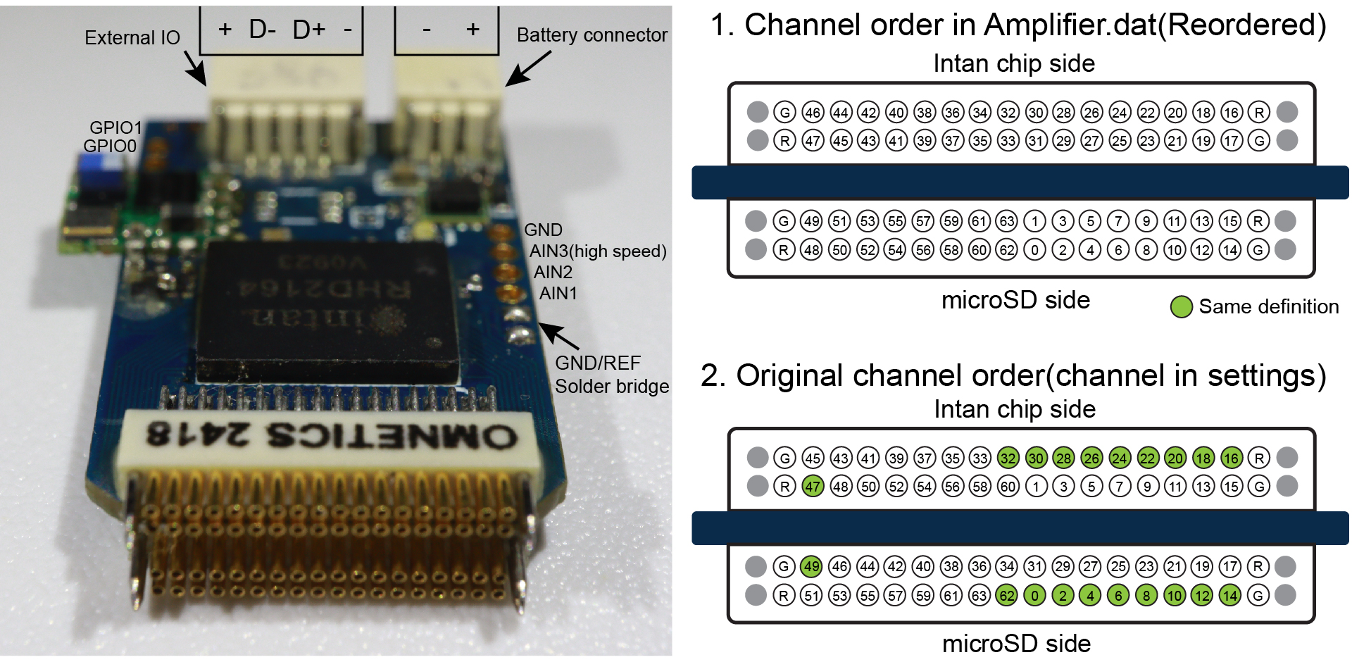
Connector images identify the stimulation, auxiliary, sensor, sync, and battery interfaces before board power-up.
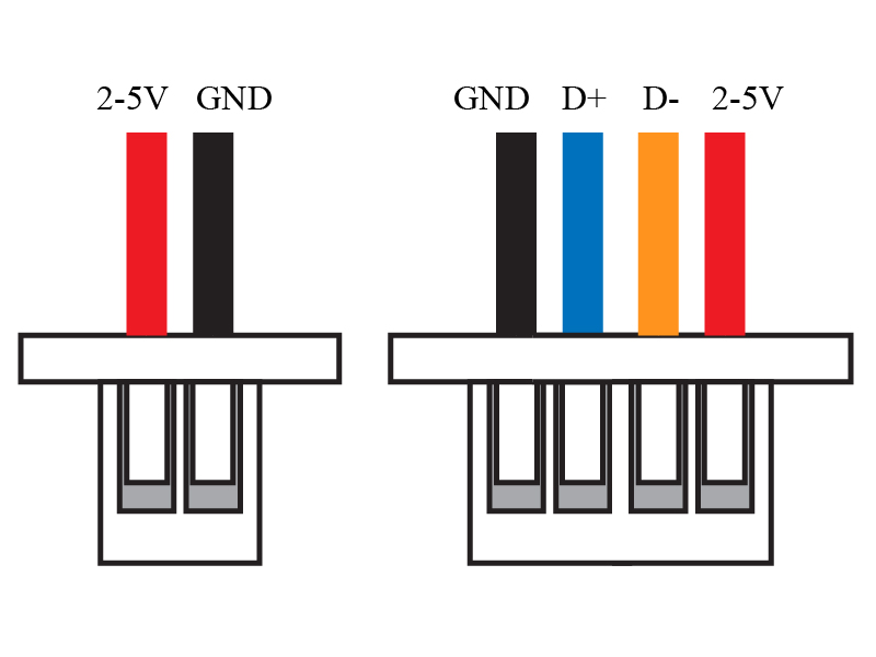
The connector-orientation schematic below highlights the power, ground, and USB data-line positions used during the first hardware check. Confirm the actual connector orientation on the assembled WILD device before applying power.
The WILD device uses these connectors to support local acquisition, storage, wireless control, synchronization, and optional stimulation in a compact head-mounted unit. Before powering the device, confirm which interfaces are required for the planned session.
Preparation Checklist
- Inspect the PCB and connectors for visible damage.
- Confirm battery polarity on the JST-SH connector.
- Insert a tested microSD card.
- Confirm the recording probe or flexible-probe connection.
- Confirm the stimulation output, IMU, microphone, camera, and external-sync connections needed for the experiment.
- Confirm that the device is running the expected released device image.
New Device Bring-Up
For a newly assembled WILD device, complete the bench power and programming checks before connecting a battery or probe.
- Prepare a 4-pin JST-SH 1.0 mm cable using the connector orientation shown above. Pre-crimped JST-SH wire leads or equivalent lab-qualified leads can be used if the polarity and pin order are verified before connection.
- Build a USB-to-4-pin test cable by soldering the JST-SH lead to a USB-A connector breakout or equivalent bench-supply adapter. Record the adapter type in local bring-up notes if the cable will be reused.
- Insert a USB power meter between the PC or USB supply and the WILD device.
- Connect the WILD device without a battery and check the first current reading. A current below 10 mA is the expected first-pass check for no obvious short circuit.
- If current is higher than expected, disconnect the device and inspect the power connector, regulator area, microSD socket, and fine-pitch solder joints before continuing.
- To enter DFU mode, momentarily short the DFU mode-select pin to VCC with metal tweezers while connecting USB. Use the connector schematic and avoid shorting adjacent pins.
- Confirm that Windows detects an
STM32-DFUdevice. If needed, install the ST DFU driver from STSW-STM32080. - In WILD Console, use a fused
.hexrelease image matching both the hardware revision (HW1 or HW2) and operating role (Auto, Master, or Slave). - Use the Console's full-flash USB path for first installation or bootloader recovery. An interrupted full-flash operation can require SWD recovery, so use stable power and USB throughout.
- After Bootloader V4 is installed, use the normal application-only USB update or the supported microSD path for later releases. See USB Mode for the current GUI procedure.
Detailed board-ordering, assembly, and special-component notes are listed in Fabrication.
microSD Card
Format the card from WILD Console before recording. The microSD card affects both reliability and power draw.
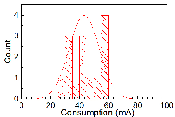
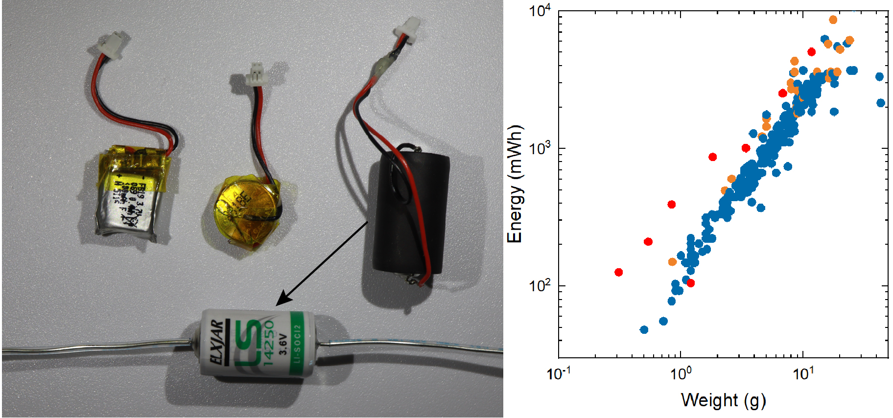
Battery and SD-card guidance are part of the experimental protocol, not optional accessory setup.
Released Device Image
Public setup documentation is based on prebuilt WILD release images. Each release image is matched to a hardware revision and experimental configuration. Keep the release tag and image filename in dataset metadata.
Release images are distributed through the latest GitHub release. Follow the release notes for the specific image used in the experiment.
Treat the released device image as part of the hardware setup record. The WILD device, WILD Console version, SD card, battery, and analysis scripts should all be traceable to the dataset.